
Wi-Fi Direct is a new technology defined by the Wi-Fi Alliance wherein capable devices can connect directly to each other quickly, securely and conveniently to do tasks such as printing, synchronization, and sharing of data. In this article we provide a thorough overview of the functionalities defined in Wi-Fi Direct Specification along with details of the underlying protocol.
More than a decade after its initial design, the IEEE 802.11 standard [1], has become one of the most common ways to access the Internet. Wi-Fi has its presence in many kinds of devices like smart-phones, TV, printers, automobiles, healthcare etc. For long wi-fi was limited to basic model of Access Points creating wireless network and Station devices connecting to wireless networks. Wi-Fi Direct allows devices to communicate directly with each other using methods similar to traditional Wi-Fi, except without requiring the use of a central access point. Instead, the devices use a “Software Access Point” (Soft AP). Direct device to device connectivity was already possible in the original IEEE 802.11 standard by means of the ad-hoc mode of operation. However this never was able to mark its presence in the market due to several drawbacks or limitations in the requirements, e.g. lack of efficient power saving support or extended QoS capabilities [2]. Latest advancement related to in the Wi-Fi device to device communications space is 802.11z, also known as Tunneled Direct Link Setup (TDLS), which enables direct device-to-device communication but requires stations to be associated with the same AP.
Wi-Fi Direct technology as described in “Wi-Fi Peer-to-Peer (P2P) Technical Specification” takes a different approach to enhancing device-to-device connectivity. Instead of leveraging the ad-hoc mode of operation, Wi-Fi Direct builds upon the successful IEEE 802.11 infrastructure mode, and lets devices negotiate who will take over the AP-like functionalities. Thus, enables legacy Wi-Fi devices to connect to the Wi-Fi Direct network, which may have not been possible otherwise.
In a typical Wi-Fi network, client scans and associate to wireless networks available, which are created and announced by Access Points (AP). Each of these devices has roles involving a different set of functionality. A major novelty of Wi-Fi Direct is that these roles are specified as dynamic, and hence a Wi-Fi Direct device has to implement both the role of a client and the role of an AP (sometimes referred to as Soft AP). These roles are therefore logical roles that could even be executed simultaneously by the same device, this type of operation is called Concurrent mode.
In order to establish a communication, P2P devices have to agree on the role that each device will assume at the time of negotiation. In the following we describe how this communication is configured using specified procedures, namely device discovery, role negotiation, service discovery, security provisioning and power saving.
Wi-Fi Direct devices, formally known as P2P Devices, communicate by establishing P2P Groups, which are functionally equivalent to traditional Wi-Fi infrastructure networks. The device implementing AP-like functionality in the P2P Group is called the P2P Group Owner (P2P GO), and devices acting as clients are known as P2P Clients.
This GO and client functionality is dynamic and is negotiated at the time of initial network setup. Two P2P devices discover each other; they negotiate their roles (P2P Client and P2P GO) to establish a P2P Group. Once the P2P Group is established, other P2P Clients can join the group as in a traditional Wi-Fi network. Legacy clients can also communicate with the P2P GO if they support the required security mechanisms. By default Wi-Fi, Direct uses WPA2PSK as a security standard. In this way legacy devices do not formally belong to the P2P Group and do not support the enhanced functionalities defined in Wi-Fi Direct, but they simply “see” the P2P GO as a traditional AP.
The logical nature of the P2P roles supports different architectural deployments; one of these is illustrated in Fig 1 represents a scenario with two P2P groups. The first scenario is a mobile phone sharing its 3G connection with two laptops; in this first scenario, the three devices form a group, the phone is acting as P2P GO while the two laptops behave as P2P Clients. In order to extend the network, one of the laptops establishes a second P2P Group with a printer; for this second group, the laptop acts as P2P GO. In order to act both as P2P Client and as P2P GO the laptop will typically alternate between the two roles by time-sharing the Wi-Fi interface.
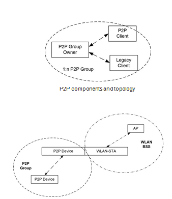
Fig.1 Wi-Fi Direct supported topologies
Source: P2P Technical Specification
Like a traditional AP, a P2P GO announces itself through beacons containing additional P2P Information Element. P2P IE is included in all management frames. Legacy devices ignore these information elements and action frames. The Wi-Fi Direct Specification requires that the P2P device which becomes the group owner should also provide the DHCP server application in their system [3] to provide P2P Clients with IP addresses. In addition, only the P2P GO can cross-connect the devices in its P2P group to an external network. Finally, Wi-Fi Direct does not allow transferring the role of P2P GO within a P2P Group. In this way, if the P2P GO leaves the P2P Group then the group is torn down, and has to be re-established using some of the specified procedures.
There are several ways in which two devices can establish a P2P Group. Three types of group formation techniques are Standard, Autonomous and Persistent cases. An example of group formation case is illustrated in Fig 2.
Group Formation procedure involves two phases-
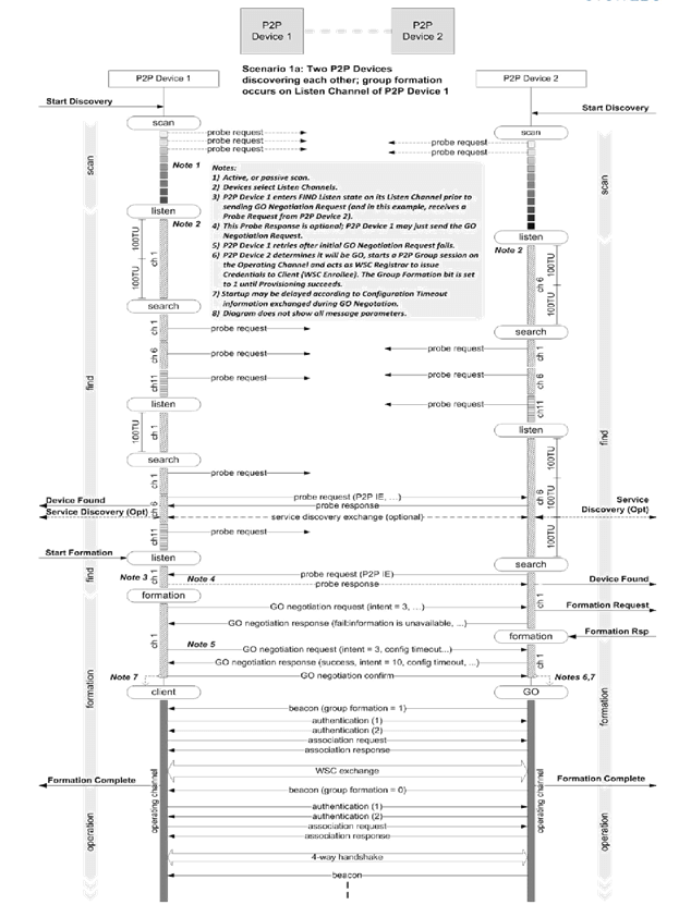
Fig.2. Wi-Fi Direct GO Negotiation and Group Formation Sequence
Source: P2P Technical Specification
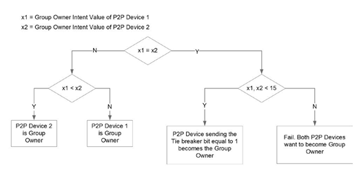
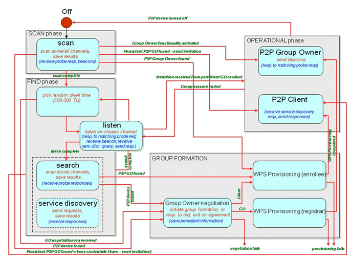
Fig.3 GO Negotiation Flow Diagram
Source: P2P Technical Specification
P2P Invitation procedure: The P2P Invitation Procedure is an optional procedure used for the following:
P2P Invitation Request: A P2P Invitation Request frame may be transmitted by:
P2P Invitation Response: A P2P Invitation Response frame (with the Status attribute set to Success) transmitted by the P2P Group Owner of a Persistent P2P Group in response to a request to invoke that P2P Group, include the P2P Group BSSID, Channel List, Operating Channel and Configuration Timeout attributes to indicate the Group BSSID, potential Operating Channels, intended Operating Channel and any GO Configuration Time.
A salient feature of Wi-Fi Direct is the ability to support service discovery at the link layer. In this way, prior to the establishment of a P2P Group, P2P Devices can exchange queries to discover the set of available services and, based on this, decide whether to continue the group formation or not. Generic Advertisement Protocol (GAS)
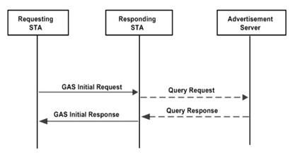
Fig.4. GAS Protocol for ANPQA P2P Client inviting another P2P Device to join the P2P Group of which the P2P Client is a member.
Source: P2P Technical Specification
Source: P2P Technical Specification
Security provisioning starts after discovery has taken place and, if required, the respective roles have been negotiated. Wi-Fi Direct devices are required to implement Wi-Fi Protected Setup (WPS) to support a secure connection with minimal user intervention. In particular, WPS allows establishing a secure connection by introducing a PIN in the P2P Client, or pushing a button in the two P2P Devices. Following WPS terminology, the P2P GO is required to implement an internal Registrar, and the P2P Client is required to implement an Enrollee. The operation of WPS is composed of two parts. In the first part, the internal Registrar is in charge of generating and issuing the network credentials, i.e., security keys, to the Enrollee. WPS is based on WPA-2 security and uses Advanced Encryption Standard (AES)-CCMP as cipher, and a randomly generated Pre-Shared Key (PSK) for mutual authentication. In the second part, the Enrollee (P2P Client) disassociates and reconnects using its new authentication credentials. In this way, if two devices already have the required network credentials (this is the case in the Persistent group formation), there is no need to trigger the first phase, and they can directly perform the authentication.
Power saving mechanisms, in current Wi-Fi networks is not defined for APs but only for clients. Wi-Fi Direct defines two new power saving mechanisms: the Opportunistic Power Save protocol and the Notice of Absence (NoA) protocol. According to rules Of P2P power management, It allow P2P GO to be
“absent” for defined periods. A legacy client expects the P2P GO to be always on to prevent use of P2P power saving in a P2P Group which contains a legacy client. The P2P GO is always in the awake power state, during the CTWindow that is necessary for discoverability & starts at TBTT. CTWindow start time and duration is advertised in beacon and probe response frames.
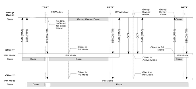
Fig.5. Opportunistic Powersave Operation
Source: P2P Technical Specification
In particular, a P2P GO defines a NoA schedule using four parameters:
A P2P GO can either cancel or update the current NoA schedule at anytime by respectively omitting or modifying the signaling element. P2P Clients always adhere to the most recently received NoA schedule. Fig 6 depicts an example operation of the NoA protocol.
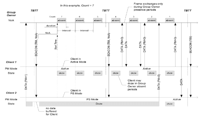
Fig.6. Notice of Absence Powersave Operation
Source: P2P Technical Specification
Wi-Fi Direct IE: The format of the P2P IE is shown in Fig 7. The P2P attributes are defined to have a common general format consisting of a 1 octet P2P Attribute ID field, a 2 octet Length field and variable-length attribute-specific information fields, shown in fig 8.
A P2P Device that encounters an unknown or reserved Attribute ID value in a P2P IE received without error shall ignore that P2P attribute and parse any remaining fields for additional P2P attributes with recognizable Attribute ID values. A P2P Device that encounters a recognizable but unexpected Attribute ID value in the received P2P IE may ignore that P2P attribute. More than one P2P IE may be included in a single frame. If multiple P2P IEs are present, the complete P2P attribute data consists of the concatenation of the P2P Attribute fields of the P2P IEs. The P2P Attributes field of each P2P IE may be any length up to the maximum (251 octets).
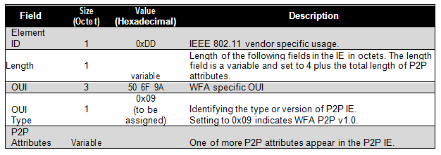
Fig.7. P2P IE Format
Source: P2P Technical Specification
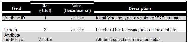
Fig.8. General Format of P2P attributes
Source: P2P Technical Specification
The P2P Capability attribute contains a set of parameters that can be used to establish a P2P connection. The format of the P2P Capability attribute is shown Fig 9.
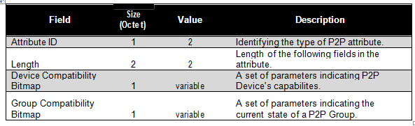
Fig.9. P2P Capability attribute format
Source: P2P Technical Specification
The Public Action frame format (as defined in IEEE 802.11k) is used to define the P2P public action frames. The general format of the P2P public action frames is shown in Fig 10.
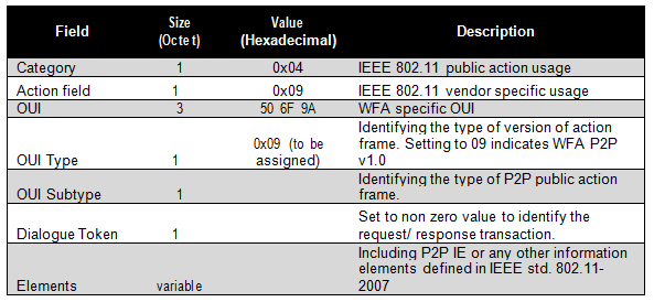
Fig.10. General Format of P2P Public Action Frame
Source: P2P Technical Specification
The Wi-Fi Direct sniffer capture is shown below. Various tools are available to capture the air packets like wireshark and omnipeek. The format of the P2P Information Element is shown Fig 11 and Fig 12.
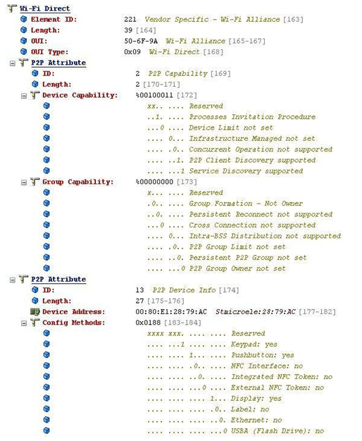
Fig.11. P2P Information Element shown from a captured Packet
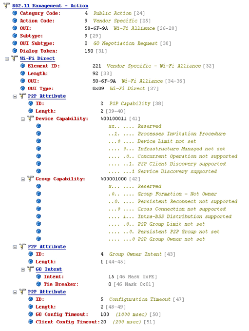
Fig.12. P2P Packet Captured with detail view as shown in Omnipeek
Testing for P2P devices involves testing of both P2P client and P2P GO. For testing of P2P client DUT is either not associated to a P2P Group Owner (GO) or if the device is already a P2P Client in a Group it uses its P2P Device Address to communicate with another P2P device.
For P2P GO testing, the device under test is acting as a P2P Group Owner of a Group. In this mode the device may have none, one or more P2P Clients or legacy STAs attached.
The WFA Sigma Automation Suite is used for the WFD Certification. This tool suite provides configuration, test control, traffic generation, and results analysis services.
P2P Device can be tested for conformance, stability and performance. Tools like Ixia Chariot are used to analyzing and measure the throughput of devices.
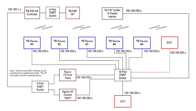
Fig.13. P2P Certification Test Configuration System