Broadband IP is a great leveling ground when it comes to converged services being offered by multiple providers. For example, with the availability of Broadband, companies such as Vonage could offer IP based phone replacement solutions threatening the turf of established phone operators. Similarly, Comcast can now suddenly offer Cable VoIP (phone service) and Verizon can now suddenly offer TV services over IP, thereby threatening each in service areas that were traditionally never their turf. Broadband IP has also enabled ‘new kids on the block’ like Skype, Joost and others to offer bundled services that threaten the trillion dollar communications industry as we know it. This is one main reason why carriers are competing to stay alive with “Quadruple Play” blended services that offer Voice, Video, Data and Wireless accessibility into one.
However, providing Quadruple-Play across heterogeneous networks (WiMAX, DSL, Cable, cellular etc.) is a non-trivial task and one needs a robust and well thought out architecture which ensures that services can be provisioned and provided uniformly to subscribers in a way that lends to seamless user experience and operator provisioning/charging and billing.
This article describes the merit of IMS (IP Multimedia Subsystem) – an over-arching architecture specification that enables uniformed IP based service delivery over diverse network types (WiFi, DSL, WiMAX, Cellular technologies etc.) as the ideal architecture for Operators to deliver Quadplay services to their users.
Uniformed Service Delivery - A Key Requirement for Quadruple Play
Uniformed service delivery is a key requirement for delivering effective Quadruple Play services.
For example, how does user “Bob”, who is watching an IPTV stream on his TV may want to ‘walk out’ of his office and continue to receive the “IPTV stream” (with possibly reduced quality) on his HSDPA cell phone. Alternately, Bob, while talking to Alice on his phone should be able to ‘handover’ his call to his desktop PC over DSL so that the existing call could be enhanced with online collaboration or photo-sharing (assuming Alice’s device supports it).
Providing a Uniformed Service Delivery architecture can be translated to the following key requirements:
Ensure subscribers and devices can be identified uniquely for the purposes of charging and delivery of services across different access mediums
Ensure security, integrity and authentication is maintained
Ensure a common Policy (QoS) and Charging architecture
Provide call continuity (often referred to as basic service continuity)
The layered 3GPP/IMS architecture attempts to enable all of the above. We will discuss in more detail how IMS enables the above and therefore is ideally suited to a heterogeneous network.
The rest of the document will provide more insight into how IMS enables the four key elements sighted above, further justifying our belief that IMS, as it stands today, is the most apt architecture for heterogeneous network deployment.
Benefits of a Uniformed Service Delivery Architecture
The benefits of a uniformed service delivery architecture are manifold:
Reduced migration cost: Legacy systems are plagued with the cost of service re-investment. For example, today, to migrate an existing DSL subscriber service to a WIFI service requires significant rework for backend provisioning systems, since the data formats are not abstracted sufficiently and the service provisioning makes direct assumptions about the access infrastructure. The IMS enabled concept of HSS data abstraction and GUP (Global User Profile) reduces this significantly.
Reduced operational service deployment cost: Any service that has been deployed at the IMS level, for example, Call Transfer will work the same way whether the subscriber is on a GPRS network, or a DSL network. This is because the IMS service execution architecture is sufficiently abstracted from the Access Network details and any access level changes only affect the respective layer nodes without affecting higher level nodes in the 3G layered architecture (a classic layered network approach)
Increased vendor interoperability: IMS defined explicit interfaces between the core network (CSCF, etc.) and the application servers, which when adhered to makes it significantly simpler for 3rd party application servers to participate in an operator network to enhance value added services to the subscriber. In fact, fortunately, in IMS, the ISC interface (which is SIP) between the core IMS network and the AS is the least complex of all other interfaces, and the authors have worked with several ISVs who have deployed services in non-IMS networks and have easily managed to deploy the same services with cellular network using IMS, by adding incremental support for Sh (Diameter for HSS), SIP header extensions and compliance to the IMS generic charging model.
Reasonably Future proof: Since the IMS architecture has already defined (or is in the process of defining) interworking profiles for a wide variety of existing access technologies, and has a generic architecture that should be able to accommodate new access technologies, this gives the architecture a reasonable insurance against disruptive network topologies that may evolve in the future (we say reasonable because future-proofing is always a best-effort activity, based on current visibility of what the future would be like)
Enabling Quadruple Play via a Uniformed Service Delivery Platform
This section delves into more details of how the IMS architecture provides an ideal platform for a enabling Quadruple Play:
Subscriber Identity
IMS has specified a generic subscriber identity mechanism that is independent of the underlying network. In addition, it is very easy to associate more than one service profile to a single subscriber. This is best described with an example:
Let us suppose that user “Joe” is an IMS subscriber. While he uses a CDMA network to connect to the IMS services, due to the limited bandwidth of the network, he is only allowed to access voice calls at a 5.3kbps codec, and basic email. However, when the same user “Joe” connects via a high speed WIMAX network, he is allowed to use a 64kbps voice codec, make video calls, and access IPTV streaming to his WIMAX device. This inherently means a few different things:
The subscriber identification should be generic so that it can be used across any access network The network needs to correlate all these scenarios to a single user “Joe”
The network needs to provide for the fact that user Joe may have one or more service profiles active at any time (for example, Joe may be registered simultaneously with both his Wimax PDA and CDMA cell phone at the same time)
It is also possible that Joe may decide to use multiple devices, hence subscriber to device mapping should not affect operation.
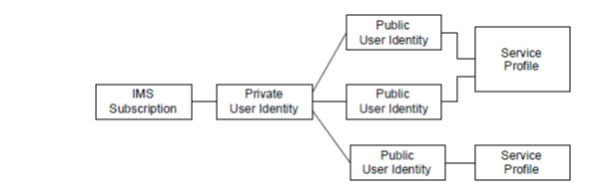
IMS solves this by introducing the concept of Public, Private URIs and Service Profiles.
All identities in IMS are standardized as SIP URIs. Using the SIP URI addressing scheme ensures that identification is independent of the underlying network. If any mapping is needed to be done, that happens depending upon the network type attached to. For example, when connected to UMTS, the URI may be mapped to an MSISDN or IMSI (for Public and Private URI).
In IMS, the Public URI is the ‘public’ address which the entity can be addressed. The Private URI is a network or operator assigned URI that ensures that the user is correctly authenticated and verified by the network (more on this later). A single Private User Identity can have more than one Public User Identity.
Finally, each Public URI can be linked to a service profile that describes the available services that are currently active for that profile. It is also possible that a single Service Profile is shared between more than one public URI.
Diagrammatically, the relationship between Subscription, Private, Public and Service profile is as below: (source TS 23.228)
One of the biggest challenges in being able to provide uniformed services across networks is to ensure that security is maintained. For a closed network configuration, ensuring security is a simpler task, since all layers are known. However, since IMS can run over multiple access networks, it is possible that some access networks provide strong security while others don’t. Hence IMS provides it’s own security negotiation at the IMS level, irrespective of underlying security negotiations that may have already taken place. For example, when a WiFi UE is first turned on, it may have already established an encrypted and secure connection with the WiFi base station. However, when that UE “registers” to IMS, it re-establishes a new set of security parameters that are visible at the IMS layer. While some may think this is duplication of security, there are several reasons why this is done:
As described previously, IMS may work over any access network type. It is possible that some access networks have weak security or no security at all. Not doing IMS level security compromises the IMS nodes as well as the subscriber profile.
It is likely that the access network may have been ‘hijacked’ – a rogue UE could impersonate another access network device if the security is not strong. Therefore, the IMS cannot assume that a ‘verified access identity’ is a ‘verified service identity’
IMS provides security, authentication and integrity in several ways:
The UE connection to the P-CSCF over the air interface (if applicable) is typically a two way IP-Sec Security Association (SA). This enables the network to verify the user and the user to verify the network as well (what if a rogue ‘network’ positions itself as the ‘real network’ for a valid user to connect to ?).
Each subscriber in the IMS network is assigned a private URI. This private URI is typically stored in the ISIM of the mobile station and is not open for public view. A rogue client will need to have access to the ISIM to impersonate the user. (Note however, that some devices may not have an ISIM. This is typically the case when an xDSL subscriber attempts to connect to the IMS. In this case, alternate security mechanisms may be used, or, a soft-ISIM – a USB stick which provides the functionality of the ISIM may also be used)
As a side note, several vendors have felt that completely independent security mechanisms at different layers, while complete does result in more cycles and delay in fast attach to networks. In situations where there is some control on the access network attachments, vendors have proposed mechanisms where security from a sub-layer is recognized and percolated at the IMS layer to reduce security negotiation delays.
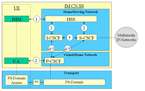
Diagrammatically, the IMS security relationships are shown as: (source TS 33.203)
Where (1) and (2) are the Private Key, Mutual authentication and IPSEC SA, while (3) and (5) deal with intra-domain security (Cx interface) (4) deals with inter-domain security.
As far as integrity and confidentiality protection goes, this needs to applied to both UE-PCSCF as well as CSCF-CSCF. The integrity protection between UE-PCSCF is based on IMS AKA (a derivative of the UMTS AKA specification). By this mechanism, both the UE and the P-CSCF verify that the data sent from each other has not been tampered with. Typically the integrity protection between CSCFs is via TLS.
Common Policy and Charging Architecture
With subscriber identity and security out of the way, the next challenge comes in providing a common infrastructure where policies as well as charging information can be regulated irrespective of the access network. This particular problem is harder than it sounds. To give the reader as flavor of its complexities, consider a case where two users are connected in a 128kbps video call over a UMTS network. The GGSN has been instructed (i.e. policy) by the CSCF to allow 128kbps of bandwidth for this particular call. Now the call hands-over to a WiMAX network. This would mean that the GGSN is no longer the policy enforcement node. That role is now played by the ASN Gateway. How does the CSCF communicate with the ASN-GW to ensure that the same rules apply ? Furthermore, how does one ensure that the charging information, that was propagated by the GGSN is continued to be propagated by the ASN-GW ? The problem is that while 3GPP specified specific rules, in release 5, about how the PDF (Policy Decision Function, usually the P-CSCF) controls the PEF (Policy Enforcement Function, usually the GGSN) in an UMTS network, there were no well defined mechanisms to abstract this interface for other access networks. Specifically, WiMAX was specified by IEEE and the network architecture is being specified by the WiMAX forum, a separate body from the 3GPP. The release 5 specific PDF-PEF functionality was not generic enough and did not yield to the WiMAX network being able to utilize all the potential advantages of a WiMAX network. This resulted in 3GPP starting an effort on a more generic ‘Policy and Charging Control’ (PCC) specification in 23.203.
The PCC functionalities are divided into two categories:
Charging control – Offers mechanisms to charge a session/stream based on Online or Offline (used for services which are paid for periodically) mode.
Policy control – Mechanisms that allow application of QoS and flow control to sessions/streams.
Talk to Our Experts Now
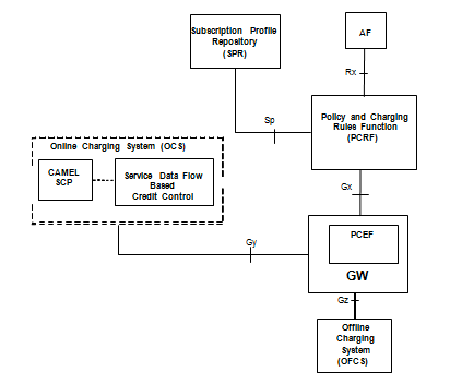
Overall PCC logical architecture (from 23.203)
The diagram above illustrates the reference architecture of PCC as defined by 3GPP. The PCRF (Policy and Charging Rules Function) is a logical entity the specifies ‘rules’ that defines how policy and charging rules are applied in the network and the PCEF (Policy Control Enforcement Point) has the role of receiving those rules and acting on them to enforce those rules.
Parameters for policy control and/or charging controls (based on detection of a service flow initiation to or from an MS) are collectively termed as a PCC rule. PCC rules are mostly IP-CAN agnostic but have some IP-CAN bearer specific elements. An IP-CAN session incorporates one or multiple IP-CAN bearers (support for multiple IP-CAN bearers per IP-CAN session is IP-CAN specific) and exists as long as a UE IP address is established.
The signaling between the PCRF and PCEF in PCC framework (Gx reference point) is Diameter based.
Since the PCRF and PCEF are ‘logical’ nodes, in reality, they could be a part of a physical node. For example, the P-CSCF could behave like the PCRF and the GGSN like the PCEF. In addition, since the architecture is intended to be access-independent, in the case of WiMAX interworking with UMTS, the ASN-GW could be the ‘PCEF’ in the WiMAX leg while the GGSN is the PCEF in the UMTS leg.
Voice Call Continuity
Voice Call Continuity, or VCC, is an area of active standardization as of today. Currently in Stage 2 specifications (TS 23.206) at 3GPP, VCC provides an architecture which allows for origination ,termination and dynamic transfer of a SIP call over IMS to a Circuit Switched (CS) call and vice versa. Simply put, if user ‘Joe’ is talking to user ‘Bob’ over IMS and in conversation, Bob roams out of IMS coverage where only CS connections are possible (or the other way around), VCC allows for a handover in a way that neither Joe not Bob experiences a call disruption.
One of the key design requirements of VCC was to try and ensure that the core CSCF nodes are not loaded with the responsibilities of call continuity and ideally, this should be an application level functionality that the CSCFs are transparent to. In an effort to meet the goal, the ‘VCC server’ is essentially a SIP B2BUA which serves as an ‘anchor’ point for all calls for a particular ‘VCC enabled UE’. This means:Any UE that requires CS/IMS call continuity needs to be aware of the ‘VCC’ application server and registers with it at the start. As a corollary, a UE must be enhanced to support VCC interfaces to be able to participate.
Any call that is made by that VCC UE is always anchored at the VCC server to ensure that proper ‘handover’ is performed in-session, if required.
At a high level, the VCC is an ‘Application Server’ that resides ‘behind’ the S-CSCF. The flow of normal signaling from UE to P-CSCF to I-CSCF to S-CSCF and then AS based on iFC is therefore preserved when it comes to IMS signaling. (Note that the VCC UE has a direct interface to the VCC-AS using the V3 reference point – this is typically realized using the Ut reference point and is related to management and provisioning of UE services, not specifically VCC related. Examples of protocols that could be applied at the Ut reference point are HTTP, XCAP etc.
So from the IMS perspective, we understand that the VCC-AS is essentially a SIP based B2BUA. But to be able to support CS calls, the VCC-AS also needs to support CS interfaces. The ‘CS’ interworking is performed by components in the VCC-AS called the ‘CS Adaptation Function (CSAF)’ and the ‘CAMEL service’. The scope of the protocol functionality of the CSAF and CAMEL services is too wide to be included in this article – therefore, sufficient to say, think of the CSAF and the CAMEL service as providing the required functionality to route CS calls, maps CS identifiers like the IMRN to IMS routes etc.
So now, we understand that the VCC-AS is a ‘B2B’ entity that offers both SIP/IMS leg and CS leg support. We now need functionality that can switch between the two, when required. The Domain Selection Function (DSF) and the Domain Transfer Function (DTF) provide this functionality – it provides interfaces and hooks to execute a call handover based on policy, provides current status of the VCC session (for example, is the UE registered in IMS in the first place to be able to switch to an IMS session?) and more.
Finally, the last question is “When does the handover occur” ? The answer to that is – Itdepends. VCC does not specify mandatory rules on detection of a handover. This is left to other protocols, either initiated by the UE or the network to decide when is the right time for a switch. Mechanisms include Media Independent Handover, link layer signal assessment and others. Remember that the goal of VCC is to be able to work over as many access networks as possible, and it is likely that different access networks may have different detection and handover policies that are better suited for those networks.
Conclusion
We explored how IMS enables key requirements for a truly convergent network architecture and further justifies why we believe that as disruptive access technologies such as WiMAX are deployed, IMS will be required as a session control architecture to be able to deliver Quadruple Play services across these diverse access technologies. When IMS was first introduced, it had several elements that were specific only to cellular networks and it was rightly felt that much of this may not be required in a non-cellular access stratum. Furthermore, there was no clear path of interworking with wireline deployments. However, as time evolved, the IMS architecture cleaned up significantly and dealt with issues of interworking with generic access stratums (wireline or wireless) as well as abstracted the architecture sufficiently to reduce dependency on specific RANs (Radio Access Networks). Obviously, the work is not completely done yet, but it is our belief that IMS is the best architecture that is available today for architects to adapt to their networks. Starting from scratch would likely result in us having to re-invent a lot of what IMS has already done.
Thank You!
Thank you for contacting us. We will get back to you soon.
X
We will get back to you!
Thank You!
Thank you for contacting us. We will get back to you soon.
 Product Engineering Services Customized software development services for diverse domains