The traditional OSS/BSS (Operational and Business Support Systems) enterprise systems and architectures currently deployed with most of the telecom service providers (TSP’s) are unable to satisfy the TSP’s need to introduce new value-added services or bundles of services at a fast pace to fight churn and ensure higher average revenue per user (ARPU).
The OSS/BSS systems for Next Generation Service Providers need to support:
Multiple Technologies/Networks
Diverse services
Complex and inter-dependent charging principles
Complex business processes
Convergent service definitions, rating, billing, and customer care
These traditional OSS/BSS architectures require a lot of custom integration effort, which makes it unsuitable for satisfying the ever-changing business requirements of telecom service providers.
This article aims to introduce a generic enterprise architecture for integrating the OSS/BSS systems for a telecom service provider. It talks about the proposed architecture, its benefits, and how it overcomes the limitations of the legacy OSS/BSS architectures. The proposed architecture is based on Service Oriented Architecture (SOA), which helps the individual components and systems be loosely coupled. The services are independent of the language in which they are implemented, the location they are placed, and the platform they are built on.
The business process workflows have been designed using Business Process Management (BPM), which makes the management and maintenance of the processes easy.
OSS/BSS Ecosystem
Fig 2.1 Traditional OSS/BSS Architecture
The term OSS describes “network systems” dealing with the telecom network itself and supporting processes such as maintaining network inventory, provisioning services, configuring network components, and managing faults.
The term BSS typically refers to “business systems” dealing with customers and the supporting processes such as taking orders, processing bills, and collecting payments.
Originally, these were mainframe-based, stand-alone systems designed to support the telecom company’s staff members in their daily jobs.
As depicted in Fig 2.1 above, these systems used to be very complex and tightly coupled with each other. A small change in one system could affect all the interfacing systems.
In today’s scenario, the next-generation service providers are required to manage a much more complex set of products and services in a dynamic and competitive marketplace. These systems ultimately help in enabling next-generation service providers to reduce costs, provide superior customer service and accelerate their time to market for new products and services.
The flow from placing an order for service to getting that activated involves various systems like ordering, inventory, provisioning, and activation.
GIS systems are used to prequalify the user credentials for the availability of the services in that geographical location. Now as everything is moving towards Service Oriented Architecture companies like Google, MapInfo, and USPS are providing web services for the validation of the user address for the availability of mobile services.
Customer Relationship Management (CRM) is a broad term that covers systems used by companies to manage their relationships with customers, including the capture, storage, and analysis of customer information. They also help the customers to log their problems and track their status.
Ordering is a key element of any service provider’s business. Ordering is where the service provider captures and manages much of the information necessary for providing a network service. The provider can keep track of customers and manage relationships with suppliers and trading partners as well.
A billing system is required for generating invoices, discounts, contracts, payments, methods of payment, etc. It interacts with the third-party payment gateway to perform the method of payment validations.
Mediation system is required to aggregate and correlate the usage records from various network elements and transform them into a common format understood by the billing system.
Provisioning enables TSPs to provide telecommunication services to a user, including everything necessary to set up the service, such as customer equipment, wiring, and transmission. In a traditional telecommunications environment, there are three separate types of provisioning: circuit provisioning, service provisioning, and switch provisioning. And, in a wireless environment, provisioning refers to service activation and involves programming various network databases with the customer’s information.
TSPs need an Inventory system to manage information about the facilities and equipment within their network. When an order is placed, other parts of the OSS, such as ordering, network design, and provisioning, must be able to communicate with the inventory system to determine whether the requested service can be supplied.
Once services have been ordered, engineered, and provisioned (or designed and assigned), the services are activated on the network.
Limitations of Traditional OSS/BSS Architecture
The traditional OSS/BSS architecture includes custom development of integration code, which is inadequate in satisfying the requirements of telecom service providers. Integrating systems when multiple TSPs collaborate is also a challenge. Common problems in traditional OSS/BSS architecture are:
Point-to-point Integration: OSS/BSS architecture involves integration with multiple external systems. For example, changes made to the CRM system by CSR needs to be updated into billing system automatically. This requires a number of interfaces between these external systems so that they can talk to each other. Such an approach is time-consuming, and integration is fragile. Furthermore, the integration does not offer an end-to-end process picture that is essential to structure and reduce integration complexity.
Tightly Coupled: Business rules and integration logic are tightly coupled with software components, and any change in the business environment will require overhauling and rebuilding the application. The OSS/BSS system is not flexible enough to handle frequently changing business requirements like introduction to new policies and service offerings.
Integration with External Systems: External systems have their legacy implementation technologies, making the interaction with them difficult and require huge development effort. Also, each external system understands its own set of data types, so a transformation model is also required to convert information from one system to another.
Complex Transaction Management: Any operation performed by an end user appears to be a single transaction. However, the corresponding changes need to be committed to multiple systems. For example, creating an account involves creating an account in the billing system, LDAP, and CRM System.
Proposed Enterprise Architecture for Integrating OSS/BSS Systems
Figure 4.1
The proposed enterprise architecture, as shown in Fig 4.1, consists of components like InAdapters, OutAdapters, Transformers, Web Services, queues and uses a BPM tool.
Business Process Management (BPM) Layer: It is used to define automated business processes. BPM systems can interact with the external systems through their off-the-shelf or custom-developed connectors. There are various players offering BPM tools, like IBM, BEA, Vitria, and Jboss. Most of the BPM tools deploy the business processes on a J2EE application server as enterprise java beans (EJB), and the whole application is assembled into an EAR. So, these business processes have access to all the J2EE server features like security, transaction, JNDI, remote connectivity, etc.
ApplicationQueue: The business processes defined in BPM can be invoked by sending a message in the Application Queue. The application queue is deployed as JMS queue on the application server in order to provide asynchronous communication.
Connector: The Connector consists of InAdapter, OutAdapter, Web Service, Transformer, and a connector specific Queue. Connector can be invoked either by placing the request in queue or by directly calling the web service. Connector is the only way through which the BPM layer can interact with the external system.
ConnectorQueue: All the asynchronous requests that need to be handled by OutAdapter need to be placed in the ConnectorQueue. Each connector has its own queue that is deployed as JMS queue on the application server.
InAdapter: InAdapter is used to place a request in the application queue that will invoke a workflow of BPM depending on the request type. For example, if account information has been updated in the CRM system by CSR, it should be synchronized with the billing system. In order to accomplish this, the CRM InAdaptor will place an updateaccount request in the application queue.
OutAdapter: OutAdapter is used to process the requests that are placed in the connector queue. Consider the same example: the CRM InAdaptor will place an updateaccount request in the application queue. Based on the message type, this request will go to the Billing queue. And, from there, OutAdapter will read the request and call the web service to create an Account in the Billing System.
Transformer: Transformer is used to convert the object of Third party system into an application-specific object, and vice versa. It has only the transformation logic and no business logic. It should be able to handle the following type of transformations:
Java Object to Java Object
Java to XML or vice-versa
XML to XML
Web Service Interface: The functionality of the external systems can be invoked through the web service interface. The Web Service interface will accept the application-specific parameters and transform them into external system-specific parameters and will then call the functionality of the external system. Similarly, the result will be transformed and returned.
Customer/Self Care Portal: It consists of custom GUI that interacts with Integration Module.
VNO: A Virtual Network Operator (VNO) who wants to use the services provided by another network access provider (NAP) may directly interact with either the exposed web service layer or the BPM layer.
Considering the example of account creation, a user will access the customer care portal to submit a request for Account creation. The AccountCreation request will be placed in the ApplicationQueue of BPM. BPM will initiate a business process defined for it. It will then place a creationRequest in all the required connector queues, like billing and CRM queue. The OutAdapter of each connectorof the respective external system will process the request placed in the connector queue and will call the web service to create an Account after the appropriate transformation. The Response of the web service will be again placed in the application queue and execution of the BPM process will resume.
The proposed enterprise architecture offers number of advantages over the traditional OSS/BSS architectures:
Whenever a new API is exposed or an existing API is changed by the third-party system, only the connector logic needs to be changed and nothing else.
All the systems are loosely coupled. Whenever a new third-party system or service is introduced into the architecture, only a new connector needs to be developed, and appropriate changes need to be made in BPM. No other system or its connector gets impacted.
There is a clear separation between business rules and integration logic. Business Rules are implemented through the business process defined in BPM, and integration is achieved through the connectors.
External system can expose its API through various interfaces like EJB, CORBA, Web service, JNI, and C++. But, with use of connector-based architecture, all the functionalities of external systems are exposed through the web services, which makes the interface to all external systems uniform.
Transactions are managed by the BPM layer. If the same business process requires interaction with multiple systems, then this is done in a single transaction. If, due to some reason, the operation fails for one of the systems, the BPM can rollback operations/transactions in other systems.
Due to the use of BPM, we can define a business process that can be used to define both manual and automated activities.
Case Study - Order Processing Using Proposed Architecture
In this example, we discuss the process flow for a typical order processing and fulfillment required by a TSP, which involves the integration of a number of systems like: CRM System, Billing System, Inventory Control System and some external systems.
The Fig 5.1 below shows the end-to-end business process flow for the ordering .
Fig 5.1 Order Process Flow
The ordering flow starts with the receipt of Customer information by the Customer Service Representative (CSR) or through the Self Care Portal. Once the details of the customer are received, the following tasks are performed till the time order gets completed:
1. CSR (Customer Service Representative) receives the customer’s relevant information. This will initiate a pre-defined business process in BPM.
2. Receipt of the customer’s information leads to Pre-Qualification of account, which includes certain checks like network/service availability in the customer’s area, validation of the customer’s address, etc. Pre-Qualification is a process in itself and starts with the validation of customer-supplied information. As a standard approach to invoke external services, BPM puts a request in GIS queue, which is consumed by the GIS OutAdapter. Like all other OutAdapters, it invokes the related (i.e. validation service) web services and puts the response in the Application queue, from where BPM picks it up and resumes the same business process.
Fig 5.2 explains the pre-qualification subprocess.
Fig 5.2 Pre-Qualification sub-process
3. Successful Pre-Qualification of a new customer leads to the creation of a customer account in the Billing system, CRM system, and other systems. To start with, Account creation sub-process puts an account creation Request in the Billing queue, Billing Out Adapter processes this request, and invokes the account creation web service in the Billing system, and places the response back into Application queue. BPM processes this response and resumes the process. If the response received from the Billing system is positive (i.e., the account gets created in Billing System) then BPM proceeds with creation of accounts in other systems, i.e, CRM system, LDAP, and Content Management system. The same process is used to create an account in all external systems, whereas account creation in internal systems is done directly, like for LDAP. However, if account creation in any of the external systems fail, then the whole process can be rolled back by BPM depending upon the rules set.
Fig 5.3 Account Creation sub-process
4. Once the account of the customer is successfully created or found (in the case of old customers), the order is created in the system followed by order validation and execution process.
5. Before the actual execution of an order, a mandatory check is performed for the customer in the billing system. This check includes checking customer’s balance, credit limit, etc. Billing connector is used for this purpose.
6. If the customer’s credentials are found valid then an Inventory check is done in the Inventory management system and relevant inventory/devices are marked reserved for the order.
7. Inventory booking is followed by the Physical Installation of devices, which are a must for the service provisioning at the client’s site.
8. A network engineer’s visit is scheduled for the physical installation of the device or customer premise’s equipment (CPE)
9. Provisioning followed by activation of services is done for the order. Provisioning includes configuring devices, network equipment, etc., for the services, and then activation of customer services is done. Here, Provisioning connector invokes various provisioning-related services provided by the Provisioning system. As a standard approach, Provisioning adapter uses its Out Adapter and puts the result back in Application Queue.
10. Provisioning and activation would require an interaction with network elements belonging to different vendors. Since, usually in a telecom network, there are heterogeneous network elements belonging to different telecom OEM vendors. There would be separate provisioning connectors for each of these external systems.
11. Once the services get activated, a notification is sent to the billing system to start the billing for the activated service. This would make sure that at the time of generation of the bill, this service is billed to the customer.
12. Activation of services necessitates the need of updating Inventory status. Hence, a notification (through Inventory connector) for updation of inventory is sent to the Inventory Management system.
13. This marks the successful completion of the order.
Conclusion
The benefits of service-oriented architecture for a telecom service provider have been made evident with examples quoted above. The use of connector-based architecture for communication to each of the external systems, like Billing, CRM etc., in the OSS/BSS ecosystem has made the architecture very loosely coupled. Any change in the external systems would be absorbed at the connector level without affecting the rest of the ecosystem. The use of a Business Process Management (BPM) tool makes the management and maintenance of the business processes easy.
This certainly adds to the advantage of TSP where the business processes are changing frequently due to changes in the market conditions, either due to the competition or launch of new services. Since the BPM tools deploy the business processes on a J2EE application server as an EAR, the architecture gets the benefits of all the J2EE server features like security, transaction, JNDI, remote connectivity, etc.
Thank You!
Thank you for contacting us. We will get back to you soon.
X
We will get back to you!
Thank You!
Thank you for contacting us. We will get back to you soon.
 Product Engineering Services Customized software development services for diverse domains

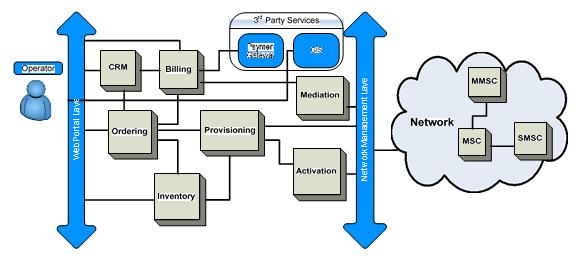
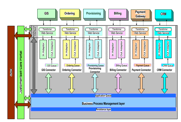
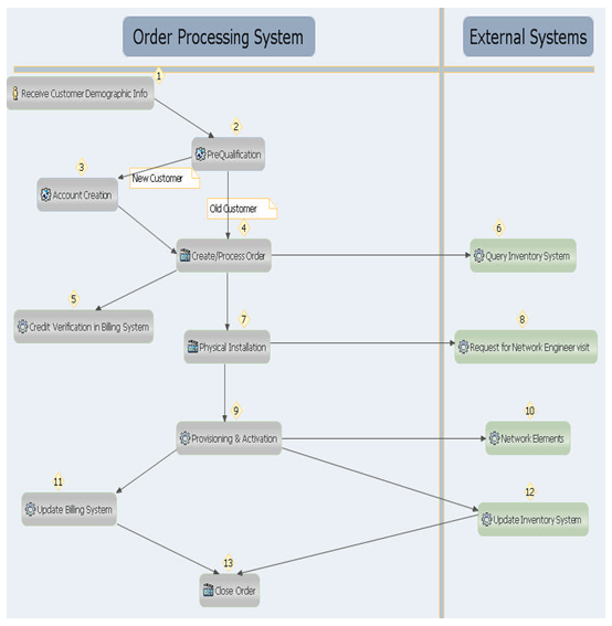
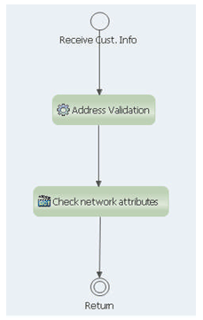 Fig 5.2 Pre-Qualification sub-process
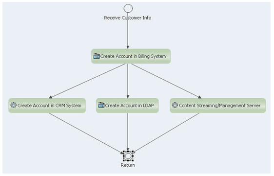 Fig 5.3 Account Creation sub-process