
December 11, 2009
For efficient Operations, network elements of a Telecom Network (e.g. Cellular Network) are integrated with Operations support Systems (OSS). Typically the OSS comes from the vendor supplying the key Access and Core network nodes of the network as these nodes are well integrated with the proprietary OSS. Invariably the Network also includes Nodes from other vendors too to provide value added services to subscribers. To get a complete view of the Network for effective Fault and Performance management, Operators & Service providers mandate the integration of 3rd Party Nodes with the existing Proprietary OSS.
Operations Support System (OSS) is huge, and several attempts to slice it into understandable pieces exist. One, which has gained a general acceptance, is the TMN (Telecommunications Management Network) model M.3100 by ITU. They introduced the “TMN pyramid” where the management is divided into a number of layers as depicted below:
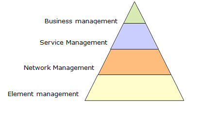
The meaning of the layers is described below. Please note that each layer is dependent on the services provided by the adjacent layer below:
Simple Network Management Protocol (SNMP) is a popular protocol for network management. It is used for collecting information from, and configuring, network devices, such as servers, printers, hubs, switches, and routers on an Internet Protocol (IP) network.
Basic SNMP components:
Each managed device runs a process called an agent. The agent is a server process that maintains the MIB database for the device. An SNMP manager is an application that generates requests for MIB information and processes the responses. The manager and agent communicate using the Simple Network Management Protocol.
SNMP agents (like snmpd daemon process) typically have predefined MIB objects that they can access. SNMPD is an SNMP agent which binds to a port (default port: 161) and awaits requests from SNMP manager. Upon receiving a request, it processes the request(s), collects the requested information and/or performs the requested operation(s) and returns the information to the sender.
An SNMP subagent is used to extend the number and type of MIB objects that an SNMP agent can support.
An SNMP manager can issue requests to an agent either to retrieve information from the agent’s MIB (an SNMP Get request), or to change information in the agent’s MIB (an SNMP Set request). An SNMP agent can also send unsolicited messages to the SNMP manager (SNMP traps).
The SNMP agent talks to both subagents and managers. The SNMP manager (which resides on one node in the network) sends requests to the agent (which resides on another). The agent sends responses and traps to the manager.
From the customer’s perspective, fault management forms one of the most important aspects to deal with in their day to day network management activities. It helps them to detect a faulty node in the network remotely and depending on the nature and severity of the alarm, actions are taken accordingly.
The fault management (FM) integration of a network node to an OSS typically means a successful integration resulting in receiving the traps from the network node (hosts SNMP agent) by an OSS (hosts SNMP manager) and displaying it on the alarm monitor with the meaningful information. The alarm monitor would be used by the network operator (FM engineer to be specific) and is responsible for the corrective actions on the faulty node thereafter.
The third party nodes may not be compliant with the proprietary OSS with respect to the format of the trap/PDU (protocol data unit). Hence, it becomes the responsibility of the OSS to convert the traps from the managed node (SNMP agent) into its own desirable format to display it on the alarm monitor. And for the SNMP get and set requests initiated by the SNMP manager, the OSS should be compliant with SNMP get and set PDUs formats specified under standard SNMP.
Some third party platforms may demand supervision of their SNMP agents from OSS. This feature is enabled from the SNMP manager and the agent should be capable enough to respond with appropriate information requested by the manager for supervision.
Fault management is an integral part of a Network Management System, and it entirely depends on the proprietary OSS as to how it would provide this feature.
Before you start the integration process, it is very important to understand the architecture of the third party node to be integrated and identify the crucial elements that can help us to appreciate the flow of the traps within their system. Help should be sought from the third party personnel in the following areas of their system:
For integration personnel, the core information of the traps that would be sent by the managed device can be known from what are called as MIB files (Management Information Base). These MIB files are provided by the system where the SNMP agent and subagents are running.
These files provide most of the information about the various traps that the system is likely to send. Apart from this, it also has information about various objects and variables of the system, and the same can be queried and set by the SNMP manager through SNMP. All these traps, objects etc are identified by their OIDs (object Identifier).
These MIB files have to be analyzed in order to understand the format of the trap PDU.
As mentioned previously, third party nodes provide the needed information through MIB files. Once the information described in the previous section has been collected, OSS needs to be configured with the same. This configuration lies within the scope of OSS as to how it would facilitate it. For example, some OSSs provide the FM integration personnel with a toolkit which assists them in configuration. Meanwhile the third party should be doing the needed SNMP configuration from their end and they should be provided with OSS details like IP address, SNMP port number where OSS listens for the traps (default UDP port: 162).
The entire process can be broadly understood with the following steps:
The third party node is added to the topology database of OSS which enables the node to be managed from OSS’s TLUI (Top Level User Interface) and to display its alarms on the alarm monitor.
Once the configuration is done, make sure that there is connectivity between OSS and the third party node over the customer’s IP network. Basic connectivity can be confirmed by using ping command. There would be a separate team at the customer’s place taking care of the network. Help can be taken from them. As mentioned above, SNMP manager listens on UDP port 162 for the traps which are being sent over the network. Hence, the managed node should send the traps to port 162.
This completes the integration task and a thorough testing should be done from both the ends. All types of alarms (critical, major and minor) should be tested to declare the integration as successful.
There are multiple challenges one faces while integrating the 3rd party nodes with OSS first time